Climbing

Midnight

Member
I did a test run today on one of our local, tough, steep climbs. Bear in mind it was too hot, and my legs are wasted from riding this week with hard efforts yesterday.

Climb is short about a mile or a little over, averages 10% with portions 15-20%.

I completed 3/4’s of the climb which included 15+% by sitting up climbing to keep
wheel contact. My lowest gearing is 34x34. I bailed out because of being too hot and too lazy to finish the last segment which is a service road with poor pavement.

Wondering, and I believe Larry mentioned at one point, wedge the seat up and the V20 is a S40. You can now climb more aggressive grades.

Has anyone done that and is it worth it?
Any dimensions on what folks have found?
I’m assuming closed cell or mini cell foam is the better product?
 

Attachments

  • IMG_7656 Copy_Original.jpeg
    IMG_7656 Copy_Original.jpeg
    1.9 MB · Views: 13

Alanczik

Member
Last weekend I climbed up a hill I was avoiding with my v20, and yes I wish I could change the seat angle at a push of a botten, steper angle at climbs, I do remember one dude here did an amazing engineering design for that exactly,

here is the full topic..


Last edited:

Karl42

Well-Known Member
Here is another solution for a variable seat angle on the V20 that can be adjusted while riding:

This comes from the german recumbent forum: https://www.velomobilforum.de/forum/index.php?threads/sitzverstellung-fuer-cruzbike-v20.63822/

I looked at both solutions posted here in detail, and might attempt to build the second one myself. For now, I can power up shorter hills by sitting up more upright, and this gives me a good core workout. But it is not really sustainable on longer rides or hills, so the variable seat angle would be really helpful there.
 

Randyc3

Well-Known Member
@Karl42, do you think Salaam Aleikum would be willing to share his CAD models? Would ask but my german is not so good.

Update-tried my German. Might have a CAD soon.
 
Last edited:

Karl42

Well-Known Member
@Karl42, do you think Salaam Aleikum would be willing to share his CAD models? Would ask but my german is not so good.

Update-tried my German. Might have a CAD soon.

Just got back from a trip. I have been in touch with Salaam Aleikum some time ago, but it now sounds like you have too. He sent me his technical drawings and additional pictures then, and I've just emailed him to ask if I can share them further.
Manufactoring the custom parts for his approach is slightly beyond my capabilities, so if you make any progress with that, I'd be very interested in that too.
 
Last edited:

Randyc3

Well-Known Member
Just got back from a trip. I have been in touch with Salaam Aleikum some time ago, but it now sounds like you have too. He sent me his technical drawings and additional pictures then, and I've just emailed him to ask if I can share them further.
Manufactoring the custom parts for his approach is slightly beyond my capabilities, so if you make any progress with that, I'd be very interested in that too.
Not sure i will be able to develop a kit, but happy to share what I learn in the process. Once i get my seat scanned(adjustable Cruzbike seat) i’ll do some preliminary CAD concepts of both approaches for the climbing seat. Cheers.
 

Randyc3

Well-Known Member
Hi,
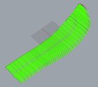
Still working on the upper seat back model. Scanning did not work as well as I hoped and there are inaccuracies in the model. I plan to use it for concept development.
 

Attachments

  • upper seat back model.jpeg
    upper seat back model.jpeg
    22 KB · Views: 11

GetBent

Well-Known Member
You all are pretty amazing. I just went with smaller chain rings, figuring that once I hit about 30 mph I will be coasting anyway...

I don't exactly have "Tour de France" quality legs.
 

Randyc3

Well-Known Member
Hi,
Still working on the upper seat back model. Scanning did not work as well as I hoped and there are inaccuracies in the model. I plan to use it for concept development.
Hi,
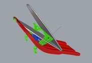
Working on the concept now.
-Support brackets will be 4 mm okumee with a layer of carbon fiber on each side.
- locking pins will be 8mm SS
-relief slots will be cut in existing seatback for brackets to move
-moving seat back will have a slight bend, unlike the one shown.
-locking pin mechanism will be attached to exiting seat back.
We’ll see how the CAD updates go.
Thanks again to Salaamaleikum!
concept development.jpeg
 

Karl42

Well-Known Member
Hi,
Working on the concept now.
Looks cool. But are you going to put the locking mechanism on top of the existing seat? Won't that raise the lowest position by quite a bit? What I liked about @Salaamaleikum 's approach is that the locking mechanism is under the seat, so the lower position is the same as the original.
Hence I'm also considering cutting the stock seat in half and then joining it with a carbon-kevlar hinge.
 

Randyc3

Well-Known Member
Hi, thanks for the comments. Yes, putting all the hardware on top of the original seat would raise seat back angle. Reconsidering now since I do want to preserve the existing aero advantage. Thinking i will use the upper half of the seat as a mould for fiberglass and carbon. Will bond in some balsa wood in the channels for stiffness. Hinge point/cut will be 10-12 inches from bottom of upper half. Will make cutout and routing holes for cable as needed since the seat back will be custom.
 

Bo6

Active Member
Hi, thanks for the comments. Yes, putting all the hardware on top of the original seat would raise seat back angle. Reconsidering now since I do want to preserve the existing aero advantage. Thinking i will use the upper half of the seat as a mould for fiberglass and carbon. Will bond in some balsa wood in the channels for stiffness. Hinge point/cut will be 10-12 inches from bottom of upper half. Will make cutout and routing holes for cable as needed since the seat back will be custom.
I would be interested in seeing a picture of the final product as I am getting a V20 frame and would like to start with a more upright seating angle.
 
Top