You are using an out of date browser. It may not display this or other websites correctly.
You should upgrade or use an alternative browser.
You should upgrade or use an alternative browser.
V20c Build Diary 2023 edition.
- Thread starter ratz
- Start date
artchris0002@yahoo.com
Member
As an alternative to your special skills as a painter, Have you used the clear Car bra auto protector material on any of your bikes? I installed some on my S40 on the forks to keep the paint looking good with the occasional rubbing of my legs. I did not install quickly enough and the black cross members have the paint rubbed off. Bummer. You don't remember me, I talked to you many years back (2016) when you lived in Eden Prairie and I just got my V20. Yes I did finally learn to ride my V20. Still in love with an inanimate object - cult type behavior I know. Just wanted to say thanks for the offer of help learning to ride my new bike.Day 1 - Praying and Peeling.
Because we are not Plastidipping the entire frame (That would be criminal on this paint job) we are going to have a devil of a time peeling the tape off and not taking the PlastiDip right off or making a ragged edge.
This is where my indecisive taping got me in trouble. I had way too many small pieces of tape and I did too many pieces at the same time.
Hind sight says do them in this order from a painting stand point
Group 1
1. Fork - 5 coats
2. Chainstay - 5 coats
Group 2
1. Frame - 7 coats
2. Seat - 5 coats
Peel tape from Each item immediately after spraying the last coat. Pastidip has a solvent on it; when you spray each new coat it all melts together. When it's wet, it peels really cleanly on the yellow tape.
I had too many dry pieces at the end. So I wound up using a clear coat top layer of Plastidip to remelt the paint so I could peel it.
Due to my sloppy tape job, I had some blemishes on the front fork (The one I peeled first and discovered the problem)
This all cost me about an extra hour and an extra can $17 of top coat. I salvaged everything, and I think it turned out pretty cool looking.
Now, I must leave it alone for at least 24 hours while it dries and hardens. There will be some edge clean-ups to do after it's dry, and then, for some longevity, I'll go over the top with a layer of clear nail polish so there is an impact layer.
The Brake cables worked, but I really don't expect those to hold up; that was a flyer. I'm still trying to figure out how I'll route those without it peeling off.
The good news is that I can take it off faster than I put it on.
I'll clean this all up this week and do a post on the wheels, and then next weekend, we'll start assembling the bike itself.
If you have any Plastidip tips, head over to this thread and share what you know....

I never look back, darling. It distracts from the now, A V20c design journal
Step 1: Get up at 6am and take (5 of 5) for a 7 mile ride up to the Top of the Dam to wear her out. Step 2: Spend the entire day preparing the build space Step 3: Accidentally spend all the rest of the free time tuning up the existing fleet of bikes so everyone can ride again tomorrow.forum.cruzbike.com
Having done this once, now I'm confident I can do the White Frame in about 4 hours without the errors and challenges peeling.
View attachment 15751View attachment 15752View attachment 15753View attachment 15757View attachment 15758View attachment 15755View attachment 15754View attachment 15756View attachment 15760
ratz
Wielder of the Rubber Mallet
Day 5 - Shoeshine
(Ah, the fun of picking up a thread after four months; I feel like Patrick Rothfuss) Yes, the bikes were built in a week, not six months.
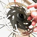
When I went to the parts bin, I realized I was going to have to buy rotors because the ones I had turned out to be 5 bolt, and these wheels need centerlock. I settled on SRAM CLX-R after much debate; when they arrived, I found them to be really well made/designed.
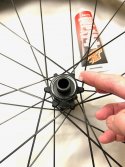
So first, we grease up the hub and slide the rotor on.
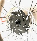
There are two types of lock rings for center lock brakes. Type 1 looks like the retaining ring for a Hyperglide Cassette and type 2 Looks like the outside edge of a Bottom Bracket. For a V20 frame, type 1 is the better choice due to its lower profile. We attempted to use type 2 on the RAMM relay bike, and under heavy side load, type 2 will have hard interference with the frame and brake assembly. There type 1 is recommended and pretty easy to source if your brakes came with the wrong kind.
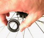
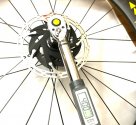
Slide the ring into place and carefully thread it with your fingers. Go slow here and make sure you don't cross-thread. No, really, go slow here. It's really easy to cross threads here, and the thread is in your HUB, and you don't want to be replacing your hub.
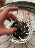
To finish up grab a cassette key and torque the unit to 40nm.
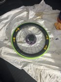
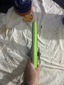
While working on the front tire, I also took the time to install the liner onto the front tire. Regrettably, The photos from this step didn't turn out very well.
The liner goes on the tire as follows: then the tire over it, and a whole lot of mess with the fluid
(Ah, the fun of picking up a thread after four months; I feel like Patrick Rothfuss) Yes, the bikes were built in a week, not six months.
When I went to the parts bin, I realized I was going to have to buy rotors because the ones I had turned out to be 5 bolt, and these wheels need centerlock. I settled on SRAM CLX-R after much debate; when they arrived, I found them to be really well made/designed.
So first, we grease up the hub and slide the rotor on.


There are two types of lock rings for center lock brakes. Type 1 looks like the retaining ring for a Hyperglide Cassette and type 2 Looks like the outside edge of a Bottom Bracket. For a V20 frame, type 1 is the better choice due to its lower profile. We attempted to use type 2 on the RAMM relay bike, and under heavy side load, type 2 will have hard interference with the frame and brake assembly. There type 1 is recommended and pretty easy to source if your brakes came with the wrong kind.

Slide the ring into place and carefully thread it with your fingers. Go slow here and make sure you don't cross-thread. No, really, go slow here. It's really easy to cross threads here, and the thread is in your HUB, and you don't want to be replacing your hub.

To finish up grab a cassette key and torque the unit to 40nm.


While working on the front tire, I also took the time to install the liner onto the front tire. Regrettably, The photos from this step didn't turn out very well.
The liner goes on the tire as follows: then the tire over it, and a whole lot of mess with the fluid


ratz
Wielder of the Rubber Mallet
Day 6 - Mock-up time
A few out-of-sequence photos here have some nice details as we assemble the frame and install the seat.
1. Use the included through axel bolt to attach the wheels so we have so rigidity to the build.
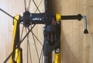
Store the include handy dandy wrench inside the axel. Amazing design idea here.
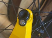
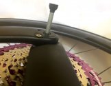
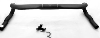
Install the handlebars with the clamp and bolts. (Use your grease and make sure you torque them correctly). After a couple of tangents and yet another failed attempt with carbon aero bars, I abandoned them and went back to my favorite Ritchey aluminum ones for a host of reasons. Which I'll post about over on the engineering thread; in the meantime you'll see these aero bars in the photos. Just know in the end they just didn't work out.
At this point we have a very Pittsburg looking bike.
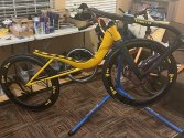
A few out-of-sequence photos here have some nice details as we assemble the frame and install the seat.
1. Use the included through axel bolt to attach the wheels so we have so rigidity to the build.

Store the include handy dandy wrench inside the axel. Amazing design idea here.


Install the handlebars with the clamp and bolts. (Use your grease and make sure you torque them correctly). After a couple of tangents and yet another failed attempt with carbon aero bars, I abandoned them and went back to my favorite Ritchey aluminum ones for a host of reasons. Which I'll post about over on the engineering thread; in the meantime you'll see these aero bars in the photos. Just know in the end they just didn't work out.

At this point we have a very Pittsburg looking bike.

ratz
Wielder of the Rubber Mallet
Day 6 - laying down on the job.
Ok, it's time to install the seat. I'm using the Cruzbike carbon seat for this build—first, some basic info. I have 20k+ miles on the stock seat and have one event on it. I like the seat for all things, excluding going uphill. After that, I have two full seasons on the Thor Sport Carbon seat, and that's the seat I have on the V20 permanently mounted on the trainer; I have enough miles on that seat that it's starting to fall apart. That seat is great for going uphill with the better ability to breathe from being more upright; however, the Thor seat leaves much to be desired from the Areo standpoint. There's a decided amount of more drag for bigger people on the Thor. Enter the new Cruzbike seat; I've only got about 400 miles on it this fall before I had to part it for travel. Early results are that this seat hits the sweet spot between Power and Aero, the best of both worlds. It did, however, take a bunch of testing to get it set to the correct length and the headrest to the right position. Since I was doing this on two bikes for 2 riders, I was able to see that, yes, getting it right makes a difference, and it did for both of us. In both case setting the seat longer than I suspected was the better choice so that the rider could sink deeper into the seat.
So with that. Grab the two halves and the mounting bolts and shim (The Carbon Seat is a separate purchase item so it will have a big C-Bracket that you won't use as that's for other frames)
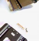
Hold the shime in the frame -
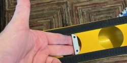
Then lay the bottom seat pan inplace and install the screw. As always use grease unless you want squeaks.
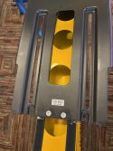
If you look closely, you will see the sticky side of Velcro. I have done enough of these seats over the years to know that the space alien wonder locking hooks known as velcro is our friend when it comes to these seats.
So, I peeled the velcro off the stock seat and installed it on the carbon seat. The CB-supplied velcro on the stock seat has great adhesive, and this can be done easily. I advise doing this and not removing the velcro from the frame; the weight hit is negligible, and you get a much more solid installation. The velcro keeps the seat and frame interface nice and quiet on the road while dampening out some vibrations.
With that done, could you bolt the front of the seat to the support wing? You want these bolts installed. With the stock seat, it was always possible to skip these due to how it was shaped. (Remember, Silvio 2.0 didn't even have these holes) but with the carbon seat, it won't stay under power if you don't install them. Also, don't add washers. Just use the pan head screws as supplied with the nylon lock nuts. If the bolts are any bigger, you will feel them through the seat pad (I don't know why, but you will. It's a princess and the pea thing, apparently).
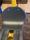
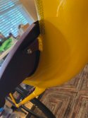
After the base is installed, install the top half, make your best guess sizewise and don't over tighten as you'll be adjusting that later
Next up is the headrest. When you first grab the headrest that comes with the seat you will be surprised. It looks flimsy, and it feels like it's not going to hold up, but once installed, it's really solid, surprisingly so, and so far on the road, it's holding up as well as the now out-of-business ADEM headrests of years past.
The headrest comes with a foam pad and cover. If you like those types of headrests, you'll like this one. However, I can't stand a wet, sweaty headrest, so I've never been partial to phone ones. I prefer a Ventisit material, so I ordered a neck roll pad (The ADEM version ) for this build.
To accommodate the installation of that neck roll, I had to drill four holes into the included plastic plate, as shown here.
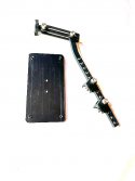
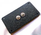
After that, it's a simple matter of bolting everything to the bike. Use red locktite for this installation, not grease. For the neck roll simply zipp time it in place.
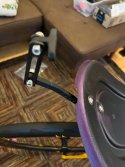
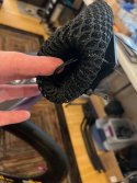
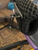
Ok, it's time to install the seat. I'm using the Cruzbike carbon seat for this build—first, some basic info. I have 20k+ miles on the stock seat and have one event on it. I like the seat for all things, excluding going uphill. After that, I have two full seasons on the Thor Sport Carbon seat, and that's the seat I have on the V20 permanently mounted on the trainer; I have enough miles on that seat that it's starting to fall apart. That seat is great for going uphill with the better ability to breathe from being more upright; however, the Thor seat leaves much to be desired from the Areo standpoint. There's a decided amount of more drag for bigger people on the Thor. Enter the new Cruzbike seat; I've only got about 400 miles on it this fall before I had to part it for travel. Early results are that this seat hits the sweet spot between Power and Aero, the best of both worlds. It did, however, take a bunch of testing to get it set to the correct length and the headrest to the right position. Since I was doing this on two bikes for 2 riders, I was able to see that, yes, getting it right makes a difference, and it did for both of us. In both case setting the seat longer than I suspected was the better choice so that the rider could sink deeper into the seat.
So with that. Grab the two halves and the mounting bolts and shim (The Carbon Seat is a separate purchase item so it will have a big C-Bracket that you won't use as that's for other frames)

Hold the shime in the frame -

Then lay the bottom seat pan inplace and install the screw. As always use grease unless you want squeaks.

If you look closely, you will see the sticky side of Velcro. I have done enough of these seats over the years to know that the space alien wonder locking hooks known as velcro is our friend when it comes to these seats.
So, I peeled the velcro off the stock seat and installed it on the carbon seat. The CB-supplied velcro on the stock seat has great adhesive, and this can be done easily. I advise doing this and not removing the velcro from the frame; the weight hit is negligible, and you get a much more solid installation. The velcro keeps the seat and frame interface nice and quiet on the road while dampening out some vibrations.
With that done, could you bolt the front of the seat to the support wing? You want these bolts installed. With the stock seat, it was always possible to skip these due to how it was shaped. (Remember, Silvio 2.0 didn't even have these holes) but with the carbon seat, it won't stay under power if you don't install them. Also, don't add washers. Just use the pan head screws as supplied with the nylon lock nuts. If the bolts are any bigger, you will feel them through the seat pad (I don't know why, but you will. It's a princess and the pea thing, apparently).


After the base is installed, install the top half, make your best guess sizewise and don't over tighten as you'll be adjusting that later
Next up is the headrest. When you first grab the headrest that comes with the seat you will be surprised. It looks flimsy, and it feels like it's not going to hold up, but once installed, it's really solid, surprisingly so, and so far on the road, it's holding up as well as the now out-of-business ADEM headrests of years past.
The headrest comes with a foam pad and cover. If you like those types of headrests, you'll like this one. However, I can't stand a wet, sweaty headrest, so I've never been partial to phone ones. I prefer a Ventisit material, so I ordered a neck roll pad (The ADEM version ) for this build.
To accommodate the installation of that neck roll, I had to drill four holes into the included plastic plate, as shown here.


After that, it's a simple matter of bolting everything to the bike. Use red locktite for this installation, not grease. For the neck roll simply zipp time it in place.


ratz
Wielder of the Rubber Mallet
Day 7 - Don't be cranky (save that for the brake bleeding)
Ok, time for the crankset.
Both bikes are getting Rotor Aldhu cranks; as discussed in the engineering thread, these are simply my favorites, and the 1x I'm even more impressed with than the 2x stuff. One of the bikes is getting a Road Axel, and the other is getting a Road Offset. The offset axle with some spacers can be made into a normal offset by countering the 2.5 bias and giving a slightly wider Q factor (152mm vs 147mm) that my legs prefer. The Road Axle is recommended for most builds; if you can't get a wide enough Q-factor with your pedals and spacers, then the Offset Axle can solve that.
For my builds, I use metal spacers and not the plastic included ones. With the torque we put into the front end of the V20 series I've found the metal ones provide a stiffer build that transfers the power really well and holds up as the miles accumulated. Since we are using Angular bearings in our Bottom Bracket, also note the inclusion of the wave washer; for that little extra bit of pre-loaded (Yes preload is built into these crank arms, but the wave washer are good insurance
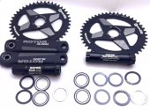
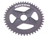
The 1x chain ring is pretty wild. It's very hollowed out for weight and it has no shifting ramps so it's all very very clean.
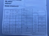
For a v20 build, the included instructions with the rotors are wrong; you will need more spacers than indicated. Here are the modified instructions for a BB386 T46
For the washers this is the line up.
Dust covers in the center; then two spacers per side and the wave washer between the two spaces on the non drive side.
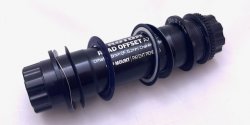
First, Grease up the axel so you can get it into the BB. You may need a few taps with a rubber mallet to get axel installed. That's normal. Just don't go all Thor on it; tap it in, don't pound it in.
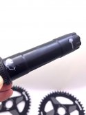
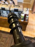
Next, install the non-drive side arm. Note the small bolt and pre-load ring before installing. Loose that bolt and spin the ring all the way down onto the crank arm. Do not make it tight. Just spin it until it's all the way down and stops. Once the crank is fully installed, you will need to spin it in the other direction with your fingers, and you'll want it to move easily in the other direction.
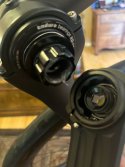
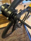
Next, you can go ahead and install the chain ring and set up the default position with OCP 3. Yep, defaults. This is a very good starting point on the V20c frame with a 1x, this is very wild, given all the fighting we have to do on the 2x setups. These builds used the 44T and 46T and based on rider heights of 5'7" and 5'9" that's how it worked out.
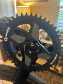
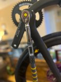
Once both crank arms are attached with lots of grease everything gets torqued to 35nm
Ok, time for the crankset.
Both bikes are getting Rotor Aldhu cranks; as discussed in the engineering thread, these are simply my favorites, and the 1x I'm even more impressed with than the 2x stuff. One of the bikes is getting a Road Axel, and the other is getting a Road Offset. The offset axle with some spacers can be made into a normal offset by countering the 2.5 bias and giving a slightly wider Q factor (152mm vs 147mm) that my legs prefer. The Road Axle is recommended for most builds; if you can't get a wide enough Q-factor with your pedals and spacers, then the Offset Axle can solve that.
For my builds, I use metal spacers and not the plastic included ones. With the torque we put into the front end of the V20 series I've found the metal ones provide a stiffer build that transfers the power really well and holds up as the miles accumulated. Since we are using Angular bearings in our Bottom Bracket, also note the inclusion of the wave washer; for that little extra bit of pre-loaded (Yes preload is built into these crank arms, but the wave washer are good insurance

The 1x chain ring is pretty wild. It's very hollowed out for weight and it has no shifting ramps so it's all very very clean.

For a v20 build, the included instructions with the rotors are wrong; you will need more spacers than indicated. Here are the modified instructions for a BB386 T46

For the washers this is the line up.
Dust covers in the center; then two spacers per side and the wave washer between the two spaces on the non drive side.

First, Grease up the axel so you can get it into the BB. You may need a few taps with a rubber mallet to get axel installed. That's normal. Just don't go all Thor on it; tap it in, don't pound it in.


Next, install the non-drive side arm. Note the small bolt and pre-load ring before installing. Loose that bolt and spin the ring all the way down onto the crank arm. Do not make it tight. Just spin it until it's all the way down and stops. Once the crank is fully installed, you will need to spin it in the other direction with your fingers, and you'll want it to move easily in the other direction.


Next, you can go ahead and install the chain ring and set up the default position with OCP 3. Yep, defaults. This is a very good starting point on the V20c frame with a 1x, this is very wild, given all the fighting we have to do on the 2x setups. These builds used the 44T and 46T and based on rider heights of 5'7" and 5'9" that's how it worked out.


Once both crank arms are attached with lots of grease everything gets torqued to 35nm
ratz
Wielder of the Rubber Mallet
Day 7 Continued - Loose ends.
After the crank arms are on, you should check for left and right slop in the install. If the assembly slides back and forth (it will), you will need to add more pre-load. You do that by turning the right below until there is no more slop. If you turn it too much, the cranks won't spin freely; if you under-tighten it, the bearings will wear, and your assembly will be loose. So spin the ring until it takes up the slack, and then tighten the bolt to keep it in place.
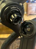
After the crank arms are on, you should check for left and right slop in the install. If the assembly slides back and forth (it will), you will need to add more pre-load. You do that by turning the right below until there is no more slop. If you turn it too much, the cranks won't spin freely; if you under-tighten it, the bearings will wear, and your assembly will be loose. So spin the ring until it takes up the slack, and then tighten the bolt to keep it in place.

ratz
Wielder of the Rubber Mallet
Day 8 - Don't Brake anything.
Next up is the basic brake setup. This has been documented many times, and while this is a hydraulic setup, this part is the same normal process at this point.
In order to get the cable lengths close to the correct starting length, we need to get the boom into a preliminary position. You can use a plum line to line up the handlebars' trailing end with the seat pan's lowest point, then tighten the pivot clamp to hold it in position.
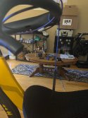
If you are using 3rd party handlebars that require cutting down the flares, this is the best time to do it. Flip the bars upside down and then use a hacksaw to cut off the handlebars to the desired length.
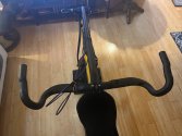
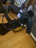
Next, secure the cable to the bottom of the boom using the combination cable holder and water bottle mount.
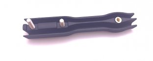
Then, install the brifters using the clamping bolts and align the brifters to the plane of the flares using a file or other straight edge. The shifting paddles should be flush with the outer edge of the flare.
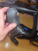
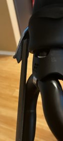
With the brifters in place, the last step is to route the hydraulic hoses as needed. If your handlebars are externally routed, then you are done. If your handlebars have internal routing, then the easiest solution is to use old brake cables if you have them.
For the cable trick, route cable from the brifter position; and into the bars using a magnet. Once the cable is out of the ingress hole, simply push the hose onto the cable gently and then guide the hose through the bar and out the egress hole near the brifters.
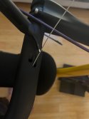
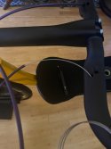
Clean up any hydraulic fluid and re-tape the hoses to prevent leaks.
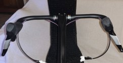
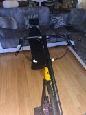
We are now ready for the fun-filled process of installing the cables and bleeding the brakes.
Next up is the basic brake setup. This has been documented many times, and while this is a hydraulic setup, this part is the same normal process at this point.
In order to get the cable lengths close to the correct starting length, we need to get the boom into a preliminary position. You can use a plum line to line up the handlebars' trailing end with the seat pan's lowest point, then tighten the pivot clamp to hold it in position.

If you are using 3rd party handlebars that require cutting down the flares, this is the best time to do it. Flip the bars upside down and then use a hacksaw to cut off the handlebars to the desired length.


Next, secure the cable to the bottom of the boom using the combination cable holder and water bottle mount.

Then, install the brifters using the clamping bolts and align the brifters to the plane of the flares using a file or other straight edge. The shifting paddles should be flush with the outer edge of the flare.


With the brifters in place, the last step is to route the hydraulic hoses as needed. If your handlebars are externally routed, then you are done. If your handlebars have internal routing, then the easiest solution is to use old brake cables if you have them.
For the cable trick, route cable from the brifter position; and into the bars using a magnet. Once the cable is out of the ingress hole, simply push the hose onto the cable gently and then guide the hose through the bar and out the egress hole near the brifters.


Clean up any hydraulic fluid and re-tape the hoses to prevent leaks.


We are now ready for the fun-filled process of installing the cables and bleeding the brakes.
ratz
Wielder of the Rubber Mallet
Day 9 - Time to Bleed.
Ok, disclaimer: brake bleeding is ...ummm...... fun; it got easier as I went, and I can do it with confidence now, but this is something you should reserve an entire day to learn and go slow. Here are two useful videos for learning the process. Please watch them a couple of times before you try.
Host shortening:
Brake Bleeding
I had to do it with the video playing and keep pausing and repeating.
And the parts you might not have:
https://www.amazon.com/dp/B00YW4L68K?psc=1&ref=ppx_yo2ov_dt_b_product_details
https://www.amazon.com/dp/B002SQZ1H6?psc=1&ref=ppx_yo2ov_dt_b_product_details
https://www.amazon.com/dp/B0BRQN5BTP?psc=1&ref=ppx_yo2ov_dt_b_product_details
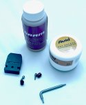
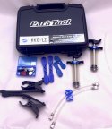
The most important item is the two red olives; don't lose them; you get one with each brake lever. They are single-use compression fittings. Once you install them, you can't remove them and reuse them. So it's important to get your hoses the right length. If you make them too long, you will need to source new olives, and that's at least a week of waiting as your local bike shops won't have them on hand (ask me how I know this). If you make your hosts two short you'll get a new set with the new hoses.
The first step is to line up your hose to the brake interface and cut it about 1 inch long
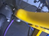
Then make sure you cut is square and make a cleaning cut if needed
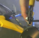
Use a hose awl to open the end if it is crushed.
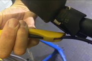
Slide the mounting bolt on to the hose
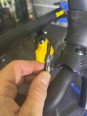
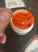
Then dip the olive mounting bolt into the dot grease (one container of dot grease should last you a lifetime)
You will want a glob of grease on the bolt.
Using the included tool screw the mounting bolt into the hole. You do not want to crush this on to the cable just make it goo and finger tight; the grease will create the seal.
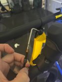
After the mounting bolt is flush, screw the olive onto the threaded end.
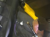
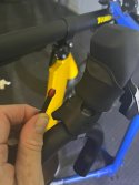
Your hose is now ready to be connected to the brifter connector barrel
Ok, disclaimer: brake bleeding is ...ummm...... fun; it got easier as I went, and I can do it with confidence now, but this is something you should reserve an entire day to learn and go slow. Here are two useful videos for learning the process. Please watch them a couple of times before you try.
Host shortening:
Brake Bleeding
I had to do it with the video playing and keep pausing and repeating.
And the parts you might not have:
https://www.amazon.com/dp/B00YW4L68K?psc=1&ref=ppx_yo2ov_dt_b_product_details
https://www.amazon.com/dp/B002SQZ1H6?psc=1&ref=ppx_yo2ov_dt_b_product_details
https://www.amazon.com/dp/B0BRQN5BTP?psc=1&ref=ppx_yo2ov_dt_b_product_details


The most important item is the two red olives; don't lose them; you get one with each brake lever. They are single-use compression fittings. Once you install them, you can't remove them and reuse them. So it's important to get your hoses the right length. If you make them too long, you will need to source new olives, and that's at least a week of waiting as your local bike shops won't have them on hand (ask me how I know this). If you make your hosts two short you'll get a new set with the new hoses.
The first step is to line up your hose to the brake interface and cut it about 1 inch long

Then make sure you cut is square and make a cleaning cut if needed

Use a hose awl to open the end if it is crushed.

Slide the mounting bolt on to the hose

Then dip the olive mounting bolt into the dot grease (one container of dot grease should last you a lifetime)
You will want a glob of grease on the bolt.

Using the included tool screw the mounting bolt into the hole. You do not want to crush this on to the cable just make it goo and finger tight; the grease will create the seal.

After the mounting bolt is flush, screw the olive onto the threaded end.


Your hose is now ready to be connected to the brifter connector barrel
ratz
Wielder of the Rubber Mallet
Day 9 - Time to Bleed. (cont)
Again the videos are your best education on how to do this; but here's the photos of how I pulled it all off.
First install the hose finger tight into the connector
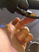
Use two open-face wrenches to tighten it together. After this step, the Olive can't be reused, and your hose length is fixed. Triple-check your lengths before you do this step.
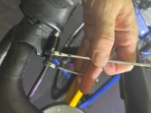
Repeat with the other hose. After which, it's time to clean up with Isopropyl alcohol. Any DEP Fluid should be thoroughly cleaned up.

Next up we prepare the syringes with the fluid. When you pick you "kit" be sure you get one with the hose clamp (blue clips on the hoses) they make the work a ton easier.
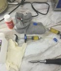
Put the wedge into the brakes to keep the pads spread.
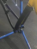
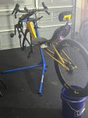
Mount the bike in the stand in the right up position. This is my traditional bucket approach to the problem.
Connect one syringe to the top of the break hood and use the holder to attach it to the handle bars.
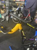
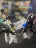
Once the top one is connected to the brifter, then connect the bottom one. Always connect the top one first.
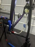
And now you are ready to bleed away. The entire process from this point on will take about 20 minutes. The swap and repeat on the other side. Most of your time will be spent on prep work, cleaning between steps, and cleaning up afterward.
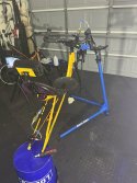
Again the videos are your best education on how to do this; but here's the photos of how I pulled it all off.
First install the hose finger tight into the connector

Use two open-face wrenches to tighten it together. After this step, the Olive can't be reused, and your hose length is fixed. Triple-check your lengths before you do this step.

Repeat with the other hose. After which, it's time to clean up with Isopropyl alcohol. Any DEP Fluid should be thoroughly cleaned up.

Next up we prepare the syringes with the fluid. When you pick you "kit" be sure you get one with the hose clamp (blue clips on the hoses) they make the work a ton easier.

Put the wedge into the brakes to keep the pads spread.

Mount the bike in the stand in the right up position. This is my traditional bucket approach to the problem.

Connect one syringe to the top of the break hood and use the holder to attach it to the handle bars.


Once the top one is connected to the brifter, then connect the bottom one. Always connect the top one first.

And now you are ready to bleed away. The entire process from this point on will take about 20 minutes. The swap and repeat on the other side. Most of your time will be spent on prep work, cleaning between steps, and cleaning up afterward.

ratz
Wielder of the Rubber Mallet
Day 10 - can we get this thing on the road?
The last thing to do is install the derailleur. This was a bit surreal for me; not having to deal with wires or a front derailleur made this part almost anticlimactic.... almost.
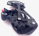
First the derailleur: The GX-APX is a beast. It's gigantic in the hand. Pictured here is the APX pairing button and the cage lock button. The spring on this thing is so strong don't bother trying to use the cage lock before it's on the bike.
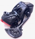
The underside has the limit screws, which thankfully use hex head bolts and not screwdriver heads, making them much easier to adjust.
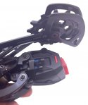
The unfortunate part is that the collar that interfaces with the derailleur hanger is small and short. When I was tuning up the chain and shifting, I cost myself about 4 hours because I mounted the derailleur with the collar in the wrong place three times. So for this part, put the bike in a stand and install the derailleur onto the hanger, then triple-check that the collar is hitting the stopping hook in one direction and free rotating in the other. On a lot of derailleurs, if you do this wrong, it just won't work; unfortunately, with this one, it will actually work; you just will never be able to get it to shift correctly across the entire range. Your clue will be that if you fix the middle gears the oter ones won't all work; and if you get the outer working the middle will then not work.
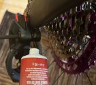
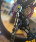
Torque the derailleur on at 5nm
Of special note is the sizing of the chain. Pictured here is how you size a chain for up to 36T cassette. Because this cassette is bigger than a 36T you need to add 3 full extra links to make it the right size. In this build picture is a stock mountain bike chain which is just a hair too short. In my case I don't like having quick links close. So I used 3 chains to make 2 final chains that are three links longer than picture here; but with the master links set at opposing sides of the chain loop.
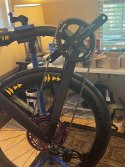
With the chain installed both bikes were ready for road testing.
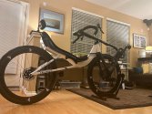
The last thing to do is install the derailleur. This was a bit surreal for me; not having to deal with wires or a front derailleur made this part almost anticlimactic.... almost.
First the derailleur: The GX-APX is a beast. It's gigantic in the hand. Pictured here is the APX pairing button and the cage lock button. The spring on this thing is so strong don't bother trying to use the cage lock before it's on the bike.

The underside has the limit screws, which thankfully use hex head bolts and not screwdriver heads, making them much easier to adjust.

The unfortunate part is that the collar that interfaces with the derailleur hanger is small and short. When I was tuning up the chain and shifting, I cost myself about 4 hours because I mounted the derailleur with the collar in the wrong place three times. So for this part, put the bike in a stand and install the derailleur onto the hanger, then triple-check that the collar is hitting the stopping hook in one direction and free rotating in the other. On a lot of derailleurs, if you do this wrong, it just won't work; unfortunately, with this one, it will actually work; you just will never be able to get it to shift correctly across the entire range. Your clue will be that if you fix the middle gears the oter ones won't all work; and if you get the outer working the middle will then not work.


Torque the derailleur on at 5nm

Of special note is the sizing of the chain. Pictured here is how you size a chain for up to 36T cassette. Because this cassette is bigger than a 36T you need to add 3 full extra links to make it the right size. In this build picture is a stock mountain bike chain which is just a hair too short. In my case I don't like having quick links close. So I used 3 chains to make 2 final chains that are three links longer than picture here; but with the master links set at opposing sides of the chain loop.

With the chain installed both bikes were ready for road testing.

ratz
Wielder of the Rubber Mallet
That's the end of the base build, but I have more coming as we work through water bottles, bags, lights, radars, etc. But up to this point, it is enough to build the bikes. The only really slow part was the hydraulic brakes. Throughout the process, I really regretted doing the hydraulic as I had options to do cable pull. Now that they are working, I'm glad I did it, but it was one of those what have I done journeys.
Here are some sneak peeks of some of what's yet to come
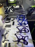
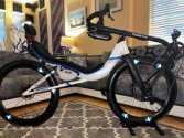
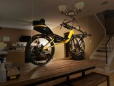
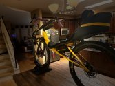
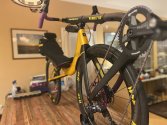
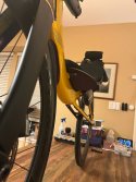
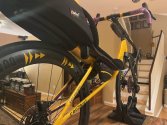
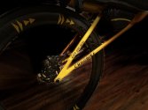
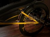
Here are some sneak peeks of some of what's yet to come


LarryOz
Cruzeum Curator & Sigma Wrangler
Bob - What crank length did you decide on for this build. It look like you can order from 150mm and upBoth bikes are getting Rotor Aldhu cranks; as discussed in the engineering thread, these are simply my favorites, and the 1x I'm even more impressed with than the 2x stuff. One of the bikes is getting a Road Axel, and the other is getting a Road Offset. The offset axle with some spacers can be made into a normal offset by countering the 2.5 bias and giving a slightly wider Q factor (152mm vs 147mm) that my legs prefer. The Road Axle is recommended for most builds; if you can't get a wide enough Q-factor with your pedals and spacers, then the Offset Axle can solve that.
ratz
Wielder of the Rubber Mallet
155 mm because the bikes on the trainers have matching cranksBob - What crank length did you decide on for this build. It look like you can order from 150mm and up
Rishi@Cruzbike
Active Member
After reading this and the "I never look back, darling. It distracts from the now, A V20c design journal" over and over, I am finally ready, and confident, to build my own V20C. Building a Value(+) 1x12 
I'm hoping to join the meetups and races in 2025.
@ratz - Thank you very much for putting these together!
@LarryOz - Thanks for taking to time to get on a call with me!
Selling my S40 if anyone is interested. See the Marketplace.
I'm hoping to join the meetups and races in 2025.
@ratz - Thank you very much for putting these together!
@LarryOz - Thanks for taking to time to get on a call with me!
Selling my S40 if anyone is interested. See the Marketplace.
DavidCH
In thought; expanding the paradigm of traversity
That is some serious bling!That's the end of the base build, but I have more coming as we work through water bottles, bags, lights, radars, etc. But up to this point, it is enough to build the bikes. The only really slow part was the hydraulic brakes. Throughout the process, I really regretted doing the hydraulic as I had options to do cable pull. Now that they are working, I'm glad I did it, but it was one of those what have I done journeys.
Here are some sneak peeks of some of what's yet to come
View attachment 16570View attachment 16563View attachment 16564View attachment 16565View attachment 16566View attachment 16569View attachment 16568View attachment 16567 View attachment 16571
ratz
Wielder of the Rubber Mallet
Winters over and so is trade so season so more to come.That is some serious bling!


