Electric 2021 Q45

bret

Well-Known Member
The space between the top of the 'slant' and the fender mounting boss (9 mm) is too narrow for a standard hose clamp (12 mm - 1/2"). I found an 8 mm hose clamp kit but that won't arrive until the end of the month. The picture shows the top and bottom are almost in line - I think as this is a permanent one-time installation it will work.
https://photos.app.goo.gl/Zzm4jnxUmgMrFxfk6
 

bret

Well-Known Member
@Tortue
I took my wheel/motor to Quantum Bicycles and Aldo thinks the best approach is to create a new left-side 12 mm thru-axle adapter with a hook that positively holds the cable away from the spinning rotor.
They have the wheel with motor now and will work out a solution (I don't have any workshop area). I'll post the outcome here, and maybe you'll want one too.
 
Last edited:

1%Grade

Member
@bret
I plan to install the Grin all axle motor on my 2021 Q45 this winter, so I’m following you and Tortue very closely. I’m very interested to see how your hook adapter works out.

I’m wondering if you’ve settled on a battery and mount. I like to carry my bike in the back of my Jeep, so I routinely remove the seat and rear wheel to fold the swing arm. That obviously adds another complication for mounting the battery under the seat. I’m thinking of a small Hailong type similar to Tortue’s first iteration, with some sort of 2 piece bracket. One piece to stay permanently on the bike. It would mount the controller, and mate with a second piece holding the battery mount (hopefully easily removed). Just wondering if that sounds crazy. I have been known to provide comic relief.
 

bret

Well-Known Member
I’m following you and Tortue very closely

I'm wondering where @Tortue is - he hasn't responded to requests for his fairing pattern yet. I live in hope, though.

I retrieved the wheel/motor/adaptor yesterday and assembled the bike. It does appear to solve the problem. Unfortunately, the Phaserunner Grin sent me does not power on. I have emailed them and await a response.

No, strike the above. Aldo of Quantum Bicycles suggested shorting the yellow & white wires buried in the heat shrink of the throttle cable from the Phaserunner. The Phaserunner manual shows these are not connected, but can be exposed and connected by a switch to provide on/off directly at the Phaserunner. Connected and soldered and now the light comes on. This bypasses the question of how it is supposed to work as provided - apparently it does for some and stopped for me. To be determined...

So, next is as below...

In the meantime, I can assemble the torque arm mounting and take pictures of that to show, and I can work out the cable routing for the motor. Quantum Bicycles told me of a local business that can apply a hard anodise to the cable protector they made - when I take the adaptor out for that I can take more photos and also use my calipers to dimension it. Quantum Bicycles did a one-off for me - if the market was large enough, they might program a CNC pattern for it.

So, I'll have some more information for you, although I do need to spend time at my job during the week.

Do you have all the components now for your motor addition? I recommend you get them as Grin is running out of stock regularly these days.
 
Last edited:

1%Grade

Member
@bret
Thanks for the update.

I don’t have my parts yet but spent lots of time on the Grin website trying to learn as much as I can. Plan to order in November when we get back to our wintering grounds in Mesa AZ. Phaserunner is out of stock right now. I need to spend time on their simulator to see if one of the lower capacity controllers will be ok.

I really appreciate you and Tortue pioneering the effort. When I bought the bike I didn’t appreciate how much the thru axle would restrict the choices for hub motors. As in restricted to one choice. Still, I love the bike and am committed to solving the problems.
 

bret

Well-Known Member
@bret
When I bought the bike I didn’t appreciate how much the thru axle would restrict the choices for hub motors.

Unless you are certain you wish to run a 72v battery, the Baserunner will handle this motor and it's more securely mounted.

This motor also has several advantages:
  1. 2kg lighter than other direct drive motors with the same power. That's 1/3 or more weight savings.
  2. Direct Drive means only main bearings to wear out - no gears. The v2 motor uses two of the same bearing - it can last a lifetime.
  3. Quiet - no gears.
  4. Direct Drive means regeneration. People get excited about this and jump into saying you won't save much power by this means. But that's not the thrill - regenerative braking is. A brake switch in the lever with this motor and controller will switch the motor from powering to braking - and it listens to the throttle. I have variable, controllable braking on my Tern S8i with this motor. Sensible riding means I may never wear out pads or rotor again - or overheat the brakes on a downhill. Any reclaimed battery charge is just gravy.
  5. Cooling with Statorade is good, and the motor will do thermal roll-back if needed.
 

bret

Well-Known Member
torque-arm-shoe-spacer.jpg torque-arm-button-head.jpg Grin All-Axle torque arm on Q45.

The torque arm is so the motor won't wind itself up and tear the cable out - instead this is the way the motor torque is transmitted to the frame. Grin supplies the torque arm with the intention it's mounted one way - this is indicated by the mounting screws, which are countersunk, and the side of the torque arm which is countersunk to receive them, and this orients the torque arm so that on the Q45 it will be above the swing arm, as per @Tortue 's installation.

But the torque is not transmitted by those screws - there are rather lobes on the hub and corresponding on the torque arm which mate. The screws only keep the assembly together. I flipped the torque arm so it is beneath the swing-arm, and fastened it with M3x12 button head screws. There is no issue with clearance for the screw heads, and the assembly does not rotate.

With the arm beneath the swing-arm, there is a side offset between the arm and the centre of the swing-arm. The shoe provided to actually connect to the frame (fork usually) has some side-to-side adjustment, but not enough. I am substituting a longer bolt and I put a washer and nut between the arm and the shoe to provide the offset.

The entire fitting is quite malleable as there is no good natural centre to the placement of the shoe against the swing-arm. The shoe is flat with small lips at the edges which will work with a range of circular forks, but doesn't find a natural match with the rather thin round lower edge of the swing-arm. I adjusted the shoe with the spacer installed so that is centred on the lower edge of the swing-arm, and then used 'metal epoxy' to create a good matching surface to mate with the lower edge of the swing-arm.

I wrapped the lower edge in food shrinkwrap, loosened the axle enough that I could rotate the torque arm, mixed two lumps of the epoxy, mashed one on each surface of the shoe (there's a space in the middle for the adjusting bolt), and then rotated the arm to mash the epoxy against the swing-arm so that the epoxy formed to the swing-arm and I let it harden. The primary force of rotation is into the swing-arm, and I ensured there was enough thickness of epoxy to eliminate any chance of weakening the middle of the epoxy 'pad'.

The two ends of the shoe provide places to seat two hose clamps which go around the entire swing-arm (or fork, usually) to anchor the shoe. The top of the swing-arm at this location has a narrow distance between the front edge of the 'slanted ramp' at the end of the swing-arm and a mudguard/fender screw boss. Most hose clamps are 12mm, which is too wide. I considered using the wire hose clamps Datsun used in their cars but the stainless steel ones are too hard to form easily to the swing-arm. Instead I found 8mm hose clamps - these are narrow enough to fit: https://www.amazon.com.au/gp/product/B07CQ4BF39/ref=ppx_yo_dt_b_asin_title_o01_s00?ie=UTF8&psc=1

I recommend a small change to this approach. When you are adjusting the shoe to centre it on the swing-arm, put it close to centre, and then measure. If you find it close to a standard metal plate thickness, substitute a square of that plate for the nut and washer I used as a spacer. Drill and tap or install a nut-sert and screw the bolt all the way through - you won't need to disassemble it again. In this way, there will be a larger flat surface for mating, which will minimise rocking due to the variable loads and help prevent the connection loosening. With that in place, then make the epoxy pads to fit your Q45.
 

Attachments

  • torque_shoe_epoxy_setup.jpg
    torque_shoe_epoxy_setup.jpg
    332.6 KB · Views: 52
  • torque-arm-hose-clamps.jpg
    torque-arm-hose-clamps.jpg
    3.9 MB · Views: 44
Last edited:

bret

Well-Known Member
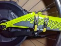
Grin All-Axle on Q45 - cable hook.

This motor works with thru-axles, but is intended for front forks. The 'All-Axle' moniker is fulfilled by interchangeable pairs of adaptors to fit the motor for the different axles.

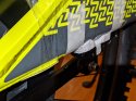
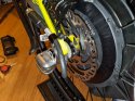
The geometry of the Q45 puts the cable dangerously close to the spinning disk rotor, which acts as a saw. Aldo of Quantum Bicycles came up with an approach of machining a new left-side axle adaptor that also sports a hook that positively holds the cable away from the brake rotor.


The form mimics the Grin-supplied 12mm thru-axle adaptor for the motor, with an Inside shaft fitting into the 20mm axle bore of the motor, an Outside shaft contacting the inside of the bicycle fork (rear swing-arm in the case of the Q45), and a flange between which stops the adaptor from sliding further into the motor axle bore.
There is a groove on the outer circumference of the Inside shaft which holds an o-ring and matches a groove inside the 20mm bore of the motor axle to act as a stop to hold the adaptor in place when the wheel is removed.

This adaptor is largely the same, except that the flange between the Inside shaft and Outside shaft is much wider (not thicker) to provide space for a hook that positively holds the motor cable away from the brake rotor.
The hook is formed by a channel cut into the flange reaching perhaps 40 degrees around the circumference of the adaptor, open to the outside, closing at the inside end flush against the Inside shaft.

I think the profile of the adaptor is two circles - one coincident with the thru-axle and wheel axis, and the second describing the outer diameter of the Hook flange, with an OD of 39.2mm.
It is not easy to determine the offset between the two axes manually with calipers, but laying out two circles with the measurements below will provide a layout that is close enough.

I DON'T measure from the 'centre' - there's a hole. I measure from either the Inside shaft or the Outside shaft to the point on the flange/Hook plate in between.

Inside shaft - probably matching original Grin 12mm thru-axle adaptor
OD: <20mm - permit insertion into bore of motor axle.
ID: 12mm - permit insertion of 12mm thru-axle used by Q45.
Depth inwards from Hook plate: ~12mm (no contact, so not critical)
End bore of Inside shaft is countersunk to avoid contact with thru-axle thread, but not so deep that it intersects the OD

Outside shaft/boss - analogous to same feature on original Grin 12mm thru-axle adaptor, but check this. I didn't.
OD: 17.1mm - probably matches Grin-supplied 12mm thru-axle adaptor
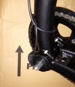
Protrusion outwards towards swing-arm from Hook plate: 2.25mm, 2.10mm, 2.14mm - not so critical as long as it's greater than the 2.1mm length. It may widen the swing-arm distance slightly.

Hook plate - formed from flange between Inside shaft and Outside shaft/boss
Thickness: 1.1mm - 1.25mm - probably can be a little thicker, I think Aldo of Quantum said it's 1.7mm, but these were my measurements. It's thin and can be bent. He sandblasted to harden it, and I had it anodised for corrosion resistance.
At closest, inside of the channel for the cable matches OD of Inside shaft - it's flush.
Channel width is <7mm, at it's closed end it is rounded, and it turns out smoothly at it's open end so that the direction of the channel is radial there.
Repeating the description above, the channel is circumferential about the 20mm OD of the Inside shaft, and as it exits to the outside this channel also turns so that the channel is radial as it exits. The turn is smooth and rounded.
However, a small segment of the exit, on the side opposite the 'point' of the hook, just at the outer edge, is straight. I don't think this is a feature, it just expands the outlet where it does not matter.

The line from the axis of the Inside/Outside shaft to the centre of the outer circle of the Hook plate appears to be through the centre of the motor cable when that is full engaged in the channel.
I estimate a 6mm offset between the two centres.

The closest approach of the outside of the Hook Plate appears to be opposite the centre of the motor cable when the cable is engaged the deepest at the end of the channel, and this is 7mm from the OD of the Outside shaft/boss.
The greatest distance is about opposite at 15mm from the OD of the Outside shaft/boss.

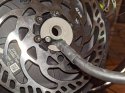
The outside of the small segment where the grub screw touches is 10.7mm from the Outside shaft/boss. You can see the grub screw in the detail - it prevents the adaptor from rotating (technically it's not a 'grub screw' - it's a countersunk screw doing duty).

The measurements just above of the Hook plate are from the Outside shaft/boss, but recall the channel for the cable is flush with the slightly larger Inside shaft so don't be confused that the width of the channel is about 6.8mm.
 

Attachments

  • outline-cable-adaptor.jpg
    outline-cable-adaptor.jpg
    5 MB · Views: 21
  • detail-cable-adaptor.jpg
    detail-cable-adaptor.jpg
    2.7 MB · Views: 23
  • adaptor-oring.jpg
    adaptor-oring.jpg
    247.5 KB · Views: 25
Last edited:

bret

Well-Known Member
Grin All-Axle with adaptor, cable mounting, and alternate showing trailer hitch.

I replaced the stock rear thru-axle with a 145mm Robert Axle Project one and use a combination of their 12mm, 6mm, and 3mm spacers to make up the difference. The outside of the swing-arm is not flat, and most trailer hitches want a flat surface to seat against. The spacers permit (I hope) a trailer hitch. This use is shown in the alternate cable routing, but should work for either appoach.

The small black clamp holding the cable to the fender/mudguard mounting boss is a 'billet P clamp' I found from an automotive store. These are used to hold small metal pipes around engines. For the alternate routing the clamp interfered with the axle spacer and I filed the corners off - shiny instead of the original black finish.

For the routing I will probably use, I moved the clamp onto the top of the swing-arm. To remove the wheel for tire changes, the sequence is:
  1. Disconnect the motor cable.
  2. Loosen the nut holding the torque arm to the shoe on the right side.
  3. Remove the thru-axle.
  4. Remove the wheel backwards and down.

To replace the wheel:
  1. Move the wheel near and engage the bolt on the end of the torque arm with the slot on the shoe on the right side.
  2. Move the wheel into place in the swing-arm. The fiddly bits are that the hub sides fit into the swing arm, the rotor fits in the brake caliper between the brake shoes, and the torque arm bolt stayed in the slot in the shoe. All three are seated at the end of this step.
  3. Replace the thru-axle.
  4. Tighten the nut holding the torque arm in the slot of the shoe.
  5. Connect the motor cable.

With the alternate routing, I would also need to disconnect the 'P clamp' from the swing-arm to free the cable, and I don't think there's any reason to have it there. Time may tell.

The Hook plate is not robust! However, it's likely to be a permanent mount, and while it's possible to bend it, it's also possible not to with a bit of attention.
 

Attachments

  • mounted-motor-cable.jpg
    mounted-motor-cable.jpg
    2.2 MB · Views: 28
  • alternate-cable-route-show-trailer-hitch.jpg
    alternate-cable-route-show-trailer-hitch.jpg
    3.4 MB · Views: 28
Last edited:

bret

Well-Known Member
My Phaserunner controller has a fault, and Grin has contacted me to diagnose and possibly replace it. I also need to mount the battery and controller.

But I tied the controller to the frame and put my battery in a pannier bag and tried riding.

The battery definitely needs to be fastened down and low is good. The battery in the bag on the rack swung and upset the handling.

But the adaptor seems to have done the job of preventing the brake rotor from contacting the motor cable. I see no marks.

The slow-wind motor has good torque and will start me from a full stop facing uphill. It does draw more than 250 watts (as does the fast-wind on my Tern S8i with 20" wheels). There is no wheel slip.

Grin recommends using a twist throttle with trigger shifters and a thumb throttle with twist shifters, and I agree with that. I used a spare thumb throttle today, but I have a twist throttle on the way.

I don't have the 24 pole PAS installed yet - I'll need to modify it to fit the oversize clamp around the bottom bracket. I'm also getting Jagwire compressionless brake housing and cable and I'll replace the brake levers with switched levers to activate the regenerative braking.
 

1%Grade

Member
Wow Bret! Thanks for the info! I need the parts in front of me to completely understand all the points you discuss, but it seems the problems are manageable.

My mechanical skills are not at your level, so I was hesitant about spending the money until I had some idea of the path forward.

I look forward to your progress on battery mount, twist throttle etc.
 

bret

Well-Known Member
My Phaserunner controller in fact appears not to have a fault. Rather I must attach the CA (Cycle Analyst) with it's multi-switch, including on-off, or I must open the wire bundle and connect the white and yellow.

Unclear at this point is that the Phaserunner has a connector for a throttle so it may be used without a CA at all. The fellow from Grin didn't say if that would suffice without also connecting white and yellow.

The white and yellow wires are hidden under shrink tubing, and are to be accessed only if the owner wants to add a physical on-off switch somewhere of their liking, so you won't see them. My local electric bike expert suggested I access them when I couldn't get my Phaserunner to power up. That did indeed permit the Phaserunner to power up.

But attaching the full CA with multi-switch also permitted it to power up with those wires separated, as delivered from the factory, so it seems it works as designed.

I did tell them I considered it a bug that their manual discusses the connections in isolation, but doesn't clarify the (at least two, and possibly three) arrangements of connections which are required for it to work properly.

Addendum: A Phaserunner with only throttle and battery connected to it does not power on. It seems either the cable must be opened to connect white and yellow (as a power on-off switch) or the CA with multi-switch including on-off switch must be connected.
 
Last edited:

bret

Well-Known Member
20km ride today using the throttle - no sign of damage to the motor cable. I think this proves the cable hook protector solution mentioned above.
 

bret

Well-Known Member
Plan to order in November

I recommend that strongly, even if you can't get everything then. According to their blog (https://ebikes.ca/blog.html) the new Baserunners are in, but Phaserunners will not be available before mid 2022.

The implication I read from this, combined with my own experience of ordering items and reading about the worsening supply chain problems is that you are not likely to get a Phaserunner at all.

The Baserunner will handle all the power the All-Axle motor can take. The motor limits mean there is no need for a Phaserunner. The only possible advantage of the Phaserunner for this is that it can work with 72v power supplies, and the Baserunner is limited to 52v.

With a 48v battery, I have had my Q45 over 40kmh now with the slow-wind motor, and I don't see the need. It's a bicycle.

In addition, partly due to irresponsible people on electric bicycles, and more due to irresponsible people on electric scooters, I'm sure we're going to get a crackdown on electric vehicles so you won't be able to use the ability. I can understand the wistful feelings, but I suggest you get a Baserunner and be happy you have an electric Cruzbike instead of nothing.

If you don't buy your battery from Grin, you'll receive a Baserunner with unconnected pigtail leads for the battery. I bought one of those locally and discovered I couldn't solder the connector on - the plastic body melted before the solder did. It's all well and good to think you'll develop the skill, but buy a handful of those battery connectors if you take that route - the lesson may be costly.

Otherwise, buy the connector from Grin and ask them to solder it for you before shipping. They can do it without fuss.

I do recommend you buy the parts as soon as you can, with a Baserunner. If you get your battery from them also, they'll install it neatly into the battery cradle as well as connecting it.
 

bret

Well-Known Member
I installed the 24 pole PAS sensor sold by Grin. It's sized to fit on a bottom bracket, but the Q45 has the chain stays attached by circumferential clamps which greatly increases the outer diameter of the assembly - the sensor will not fit unless the flange on it is removed. I sawed this flange off, and I also reversed the sensor so it's bulge was to the outside, and clears the crank arm. A long ride today proves out the installation.

Grin sells 12 pole PAS sensors as well, and I can't say if either would fit in this situation. The benefit of having twice as many sensor poles suggests not trying. One of the settings in the Cycle Analyst permits reversing the rotation of the sensor, as it might be installed on the right or left - check this or your bike goes backwards.

In this picture, you can see the scars where I removed the flange.
 

Attachments

  • 24Pole_closeup_20211028.jpg
    24Pole_closeup_20211028.jpg
    622.7 KB · Views: 20

bret

Well-Known Member
I have been out of commission with an injury so haven't posted.

The battery cradle mount is installed on the rear swingarm using the rack mounting bosses, and the under seat rack with it. The battery strapped to the rear cargo carrier seriously wagged the tail of the bike in operation, and I plan to only put large light bulky items there in the future. For me, the under seat rack is the place for anything heavy - I don't notice the battery in handling (4+ kg). My Phaserunner controller is mounted inside the battery cradle mount - these controllers are not available until mid-2022 (supply chain issues), but the Baserunner is, and that fits entirely in several of the standard battery cradles available - Grin will mount it if you buy the battery from them.

I have Pedal Cadence Assist, switched brake levers to signal to the controller, and a thumb throttle on the left. I'm not using Torque sensing Assist, as I have joints that won't take loads so can't signal by pushing harder. The Cadence assist can be configured in the controller - mine adds more assist at higher cadence, which matches the idea of shifting down for hills. As I ride more, I'll do experiments and dial in the profile to fit me - but you don't have my body.

I read a recommendation of thumb throttle for grip shift, and handgrip throttle (a la motorcycle) for trigger shifters so I ordered one to try but I've discarded that. For me, the addition of motor-powered braking, and to a lesser extent wanting to maintain throttle while shifting, changes the picture.

I have my brake cables adjusted so there is a small 'dead zone' at first - but the electric switch closes in this zone, so the controller knows I want to brake. It takes drive power off the motor, and instead reverses to a configurable level. The PAS Cadence sensor (or torque sensor if I had one) is ignored, but the throttle can instead decide the amount of reversing/braking force. All without touching the brake pads or rotor...

My Q45 has trigger shifters on the right, and thumb throttle on the left. I want to down-shift while I'm braking sometimes. My right hand just starts pulling the brake lever, triggering the switch, the left thumb throttle becomes the signal how hard to brake, and my right thumb can shift down while spinning the pedals has no effect on motor input.

To brake, I am training myself to just barely pull the right brake lever (icon shows on the CA display when the switch triggers) and use the throttle to tell the motor how much to brake. This will stop the bike, although in a crunch, I'll hammer both physical brakes to stop. Most of the time, I don't put any wear on the brake shoes or rotor, so won't need to adjust them or replace them.

And I'm putting power back into the battery each time, extending my range for free (if we ignore spending the money on the motor, etc.).
 

bret

Well-Known Member
@1%Grade there is a 25% off sale on Grin All-Axle motors to 31 December if you haven't yet purchased. If you have, beg - it might work. Offer to buy more stuff for the store credit they give you.

You mentioned you commonly fold your swingarm to fit in your vehicle. I don't have photos yet, but the battery rack design I accepted won't permit that. I am using the under seat rack and my battery rack also mounts to the same bosses on the swingarm.

Perhaps you should use @Tortue 's original design (but read on) and ensure the battery rack/cradle is narrow enough to clear the inside of the swingarm. The standard Hailong case Grin provides which also neatly fits their Baserunner controller should easily clear.

Maximun excursion of the swingarm in operation is 165mm between the shock mounting bolt centres, so that plus a bit of leeway (metal is springy and bends a few millimetres) will define the angle of the back of the bracket to clear in un-folded use.

However, when you remove the shock to fold the swingarm, the kickstand mount cross piece will need to clear the back end of the battery bracket. This may not be possible - I don't have it in front of me.

A solution that will work for my or @Tortue 's battery mount is to just pull the 4 bolts holding the battery bracket and move it out of the way, then reassemble it. You want to have those tools anyway, it doesn't take long, and it could be less stress than over-thinking the battery rack design. You are already pulling the seat, shock, and maybe rear rack now to do this.

Mechanic's hints:
  • Threads not intended for routine disassembly get non-permanent Loc-tite (not so important for bicycle use, but good for peace of mind sometimes - I always use it for electric motor mounts and brake rotors). Watch out - there are permanent thread-locker compounds! Read labels.
  • Threads commonly disassembled get greased! - greatly helps prevent cross-threading, corrosion jams, and wear (important for bicycle use). They will hold just fine - they are designed for this. Everyone should be doing this all the time - unless you know a clear reason not to, threads get greased. Wipe away the excess after.
  • Get a small torque wrench for these bolts so you won't stress about over-tightening them. I have a Feedback Sports 2-10 N-m wrench with replaceable bits and rated to 60 N-m for disassembly work.
Topeak has some nifty portable fixed torque wrenches. Pick the bolt size - buy the adaptor that matches the designated torque for that size, plug it into the handle, insert the bit and tighten - you will feel a positive 'click' at the right torque - you're done! Park tools has some nice ones too.

You won't strip a bolt again - saves hair.
 
Top