Rotor Q rings setting

Bo6

Active Member
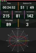
I have my V20 on the trainer and am using rotor Q Rings and a Rotor 2INpower meter. It gives a nice graph of the of the power on all positions of the peddle stroke.

I wonder if anyone out there has had any experience with setting calibrating the system? I am trying to get the best position (OCP) for the chainrings. In the calibration setting Rotor advises starting with the left crank vertical with the peddle down. It seems to me that this may be wrong for a recumbent as my graphs are very different from Rotor's examples. I am currently using OCP 3 as per recommendations from rotor.

I have only just started using the power meter and it seems to work well, but I think a little fine tuning is in order. I have a few questions in to rotor technology and their answers do not seem to recognize recumbent differences. Any help would be appreciated.
Bob
 

Henri

scatter brain
You can completely ignore
the general advice for where to start trying. I have not yet tried it with Rotor and power meter, but for the rough possibilities of a 5-bolt mount I could just feel what direction I want to change it in and was happy with effective 36° of jump between adjustments. I am curious to see what the power meter analysis looks like, if it can be translated to use on the recumbent. I have those things on order as well, but it will be a while before I can start using it.
 

LarryOz

Cruzeum Curator & Sigma Wrangler
This, which if you cross check with the pedal stroke should be at the point where you are delivering the most power.
Exactly - and that is the whole point of the Q-rings.
Although I will have to say I have ridden lots of miles with and with-out, and tested power output , speed, etc in many ways.
I can truthfully tell no real difference.
I like the visual way the ring rises and falls as I pedal - but not sure just that is worth the price! :)
 

Bo6

Active Member
Thanks for the comments.
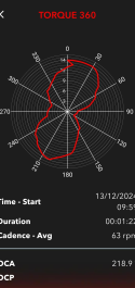
I think the issue is finding the "0" point for calibration. Rotor uses Left pedal in the down vertical position for DF bikes. And their app gives a graph as below. showing the max torque and OCP #.


1734111362418.png
With this setup my graph is shown below. It looks like the max torque is ~ 20degrees which would agree with the V20 layback angle. I think I'll try zeroing the peddles using this angle and see how it works.

I know it may not be worth the $ spent to have all this data, but it interesting and a bit of fun to play with. I do see the angle change as I put more power to the peddles as it would climbing a hill. I also can "see" my peddling raggedness, which should help me get a bit smother.

Yes, I have heard the expression "more money than brains" ;-)

1734113210101.png
 

Henri

scatter brain
Your graph confuses me. Between roughly 0° and 7° it shows three values. XD Is that a thing they do or does this only happen on recumbents, for which it wasn't built?
 

Bo6

Active Member
Your graph confuses me. Between roughly 0° and 7° it shows three values. XD Is that a thing they do or does this only happen on recumbents, for which it wasn't built?
The power meter is 2 sided and measures torque applied to the peddles through the entire rotation, both left and right sides are displayed. The graph shows torque vs the peddle angle. Torque is plotted form 0 in the center and increases to the outer circle. Peddle angle is determined by zeroing the crank during calibration. It is independent of XD.
 

Henri

scatter brain
measures torque applied to the peddles through the entire rotation, both left and right sides are displayed
But it doesn't display left and right individually; it adds them togeter. You could have two lines seperate (both with one blob) or one line of the summ (with two blobs). In no case should one line have more than one torque value per crank position.

Torque is plotted form 0 in the center and increases to the outer circle.
Yes. And when you read at for example 3°, you will find the line in three different hights.

Peddle angle is determined by zeroing the crank
You need to put it vertical and tell it, that this is what vertical looks like and it counts from there?

It is independent of XD.
Are you talking about SRAM freehub bodies?? I was using it as the emoticon.
 

Bo6

Active Member
But it doesn't display left and right individually; it adds them togeter. You could have two lines seperate (both with one blob) or one line of the summ (with two blobs). In no case should one line have more than one torque value per crank position.


Yes. And when you read at for example 3°, you will find the line in three different hights.


You need to put it vertical and tell it, that this is what vertical looks like and it counts from there?


Are you talking about SRAM freehub bodies?? I was using it as the emoticon.
opps may have hit the wrong key.
At 3deg I may nave back peddled an instant. When you see the actual app the graph is constantly following the rotation, the images are screen shots. When zeroing the left crank is supposed to be down and this appears to define the 90 deg position. Sorry did not know what you meant by XD, had me wondering :)
 

Henri

scatter brain
Ah, it's just showing latest rotation? I assumed it was the average of a recording period. If you actually rotated back a bit, it would be understandable. Wrong, because you didn't have that torque for that bit of rotation, but it just connects the usefull data points with a straight line.
 

Codysia

New Member
Hey Bob, I've used Rotor power meters on my recumbent before, and I agree that the standard calibration advice doesn’t always work great for our setup. The left crank vertical with the pedal down isn't always the best starting point because the pedal stroke angle is different on recumbents. When I was dialing mine in, I played around with different OCP positions and did some test rides to see how the graphs looked in comparison to my effort. It took a bit of tweaking, but eventually, I found a position that felt more consistent with the power data. Definitely a bit of trial and error, but it should make a difference.
 
Top