egervaswatson
New Member
I wanted the S40 for touring, and for me part of that was always going to be towing a trailer. I have two trailers--the Topeak Journey and the Bob Yak. My ideal trailer hitch was going to be one that could work with both trailers and would be very sturdy, without modifying or putting large amounts of torque on any part of the frame.
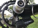
To prevent a lot of torque on any braze-ons, I wanted two points of attachment, one of them preferably being the rear axle. I designed and 3D printed several iterations of a tab that would span the quick-release and the fender bosses on the rear fork. Once I had a shape that fit perfectly, I sent the CAD model to my brother, who CNC machined it out of aluminum, resulting in the following parts:

Since these were machined by CNC, where I wanted to tap threads I was able to spec the holes to the exact tap drill diameter.
The stock rear skewer for the S40 is too short to accommodate an extra 3/8" of stock. I bought a standard "rear" skewer, but this was, in turn, too long. I used an M5 die to thread the skewer further up its length.

Now I could clamp the hitch mounts to the rear fork, but there was still a lot of excess length on the skewer. Normally, cutting a threaded rod absolutely destroys the threads, making it very hard to use the bolt from then on. To prevent this, I threaded my die onto the skewer, cut and chamfered the excess off, then threaded the die back off to clean up the threads.

On a hitch mount design for a previous bike, I simply drilled out holes for the M5 bolts, but this resulted in a small amount of slop. This time, I decided to thread the holes to eliminate any slop whatsoever. Of course, if the threads on the hitch didn't line up with the threads on the bike, I'd be in trouble--so I clamped the hitch mount in place (with thin nylon spacers to protect the paint), carefully threaded my tap into the fender boss, then proceeded to cut the threads into the hitch mount.

No room between the dropouts for a tap wrench, but that's why God invented visegrips.
I threaded in the M5 machine screws,found that they fit perfectly, and tapped the holes for the actual hitch bolts. This served to eliminate slop and let me use a single nylock on the back side in a jam nut configuration to ensure zero risk of loosening up.

With all the metal components working perfectly, all that remained was to 3D print the actual hitch bushings. Designing them to accommodate both trailers resulted in an interesting vase-like design, but one that works flawlessly.

Bare Hitch.

With Topeak Journey.

With Bob Yak.
For additional cargo capacity, I also wanted a rear rack. The stock rack for the S40 is fine, but I really wanted something that would accommodate my Topeak shopping basket for grocery runs. I therefore decided to use a Topeak seatpost rack. The problem, of course, is that the S40 doesn't have anything that really resembles a seatpost.
I replaced the bolt that holds the headrest in place with a much longer one so that I could use that as the top anchor point for my "seatpost". Of course, seatposts aren't usually straight up and down, and racks designed to clamp to them take this into account. I therefore 3D printed 2 70° shims that would clamp my stock between them, holding it at a precise angle.

One point of attachment on a piece of 1/16" aluminum wasn't going to cut it, so I added two struts supporting it against the braze-ons near the top of the seat stays.

To prevent a lot of torque on any braze-ons, I wanted two points of attachment, one of them preferably being the rear axle. I designed and 3D printed several iterations of a tab that would span the quick-release and the fender bosses on the rear fork. Once I had a shape that fit perfectly, I sent the CAD model to my brother, who CNC machined it out of aluminum, resulting in the following parts:
Since these were machined by CNC, where I wanted to tap threads I was able to spec the holes to the exact tap drill diameter.
The stock rear skewer for the S40 is too short to accommodate an extra 3/8" of stock. I bought a standard "rear" skewer, but this was, in turn, too long. I used an M5 die to thread the skewer further up its length.
Now I could clamp the hitch mounts to the rear fork, but there was still a lot of excess length on the skewer. Normally, cutting a threaded rod absolutely destroys the threads, making it very hard to use the bolt from then on. To prevent this, I threaded my die onto the skewer, cut and chamfered the excess off, then threaded the die back off to clean up the threads.
On a hitch mount design for a previous bike, I simply drilled out holes for the M5 bolts, but this resulted in a small amount of slop. This time, I decided to thread the holes to eliminate any slop whatsoever. Of course, if the threads on the hitch didn't line up with the threads on the bike, I'd be in trouble--so I clamped the hitch mount in place (with thin nylon spacers to protect the paint), carefully threaded my tap into the fender boss, then proceeded to cut the threads into the hitch mount.
No room between the dropouts for a tap wrench, but that's why God invented visegrips.
I threaded in the M5 machine screws,found that they fit perfectly, and tapped the holes for the actual hitch bolts. This served to eliminate slop and let me use a single nylock on the back side in a jam nut configuration to ensure zero risk of loosening up.
With all the metal components working perfectly, all that remained was to 3D print the actual hitch bushings. Designing them to accommodate both trailers resulted in an interesting vase-like design, but one that works flawlessly.
Bare Hitch.
With Topeak Journey.
With Bob Yak.
For additional cargo capacity, I also wanted a rear rack. The stock rack for the S40 is fine, but I really wanted something that would accommodate my Topeak shopping basket for grocery runs. I therefore decided to use a Topeak seatpost rack. The problem, of course, is that the S40 doesn't have anything that really resembles a seatpost.
I replaced the bolt that holds the headrest in place with a much longer one so that I could use that as the top anchor point for my "seatpost". Of course, seatposts aren't usually straight up and down, and racks designed to clamp to them take this into account. I therefore 3D printed 2 70° shims that would clamp my stock between them, holding it at a precise angle.
One point of attachment on a piece of 1/16" aluminum wasn't going to cut it, so I added two struts supporting it against the braze-ons near the top of the seat stays.
Last edited: