super slim
Zen MBB Master
That's a creative colour scheme for a wheel set!!
What colour is the frame?
What colour is the frame?
Those are for the Yellow one.That's a creative colour scheme for a wheel set!!
What colour is the frame?


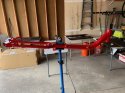
 The top section of my boom is attached upside down on the clamp that connects to the upper part of the front fork. It came from the factory that way.
Where is the Rubber Mallet?Always interesting to work through a bike for the first time; it took a few hours but the curve wasn't too bad and the results came out pretty good. Really love the tires they are like having suspension.
View attachment 7902 View attachment 7903 View attachment 7904 View attachment 7905 View attachment 7906 View attachment 7907 View attachment 7908 View attachment 7909 View attachment 7910 View attachment 7911
Good to see you still have it!@super slim (@ratz)
Found it! In the 4th picture of the last set of his pictures at the bottom. This one (oops can't figure out how to get the thumbnail to go here):

View attachment 7912 The top section of my boom is attached upside down on the clamp that connects to the upper part of the front fork. It came from the factory that way.
There appear to be two bolts holding the boom to the clamp. Is it possible to take these bolts out and correct this problem?
I have pulled on them pretty hard in the normal counterclockwise direction but could not get them to budge. I would like some assurance that I won’t break anything and that the bolts aren’t threaded in the opposite direction before I try more torque.
Everyone else shows builds where the shift and brake cables run in the gap between the boom and the fork clamp. With mine, the cables would be pinched. So I have to run them outside and use zip ties to hold them.
@ratz and @Robert Holler can you guys give me any advice on whether this is fixable at home or I just have to live with it?
Good to see you still have it!
Its edges look very sharp, so not much use!!!!!
Are you getting better at fitting bike bits together, after 10+ bike full builds?
Thanks for letting me know about the red lock tight. That means I will have to live with it.Your part is correct (the two angled edges are opposite each other). You may have it installed upside down. This setup was used on a lot of previous models. Not a builds have room for the wires if you have long legs. You can remove the bolt but it is installed (in my experience) with red lock tight and darn hard to remove. I did it once and will never try again wasn’t enough benefit. You can fix the wires by using bar tape to strap the to the vertical riser


Thanks for letting me know about the red lock tight. That means I will have to live with it.
Yes the first picture showed it upside down, but if you look closely you will see that on your bike, the angled side of the end piece is on the top and the side parallel to the boom is on the bottom. Mine is flipped over. This appears to be a clear mis-build from the Kickstarter deliveries. If the orientation didn’t matter the the bracket should have been symmetric View attachment 7920
My T50 is now a T20
I want to find a stem with less rise to match the boom angle.View attachment 6133
- Silvio bars
- 1 x 11 drivetrain
- 150mm cranks
- Carbon Seat
- Ventisit seatpad
- 26x2.3" tyres
do you have a pic of your complete Cruz-MooseEnough playing around. Time to get out the pipe cutter.
Ah that would be because I didn't post the unfinished bike. You are correct it changed between the KS run and the stock run. (For others following along, If you had to cut your riser and fork steam then you have post run) In this case the Red bike has the post run, and the yellow has the KS run. I swapped them as the yellow was started first and I didn't feel like cutting the fork.
I'm sure the clamp was engineered for strength in this new design, (the old ones where symmetric). But I don't know that it matters until you get to the 300watt power range. I do know that the boom is designed for the angled side to be up. So you should probably flip your clamp. On the old Quests you couldn't get it confused because it had marks on the boom to indicate how far you have it inserted, it you put it angle side down; then you couldn't read the etching.
The other two changes where that the lock clamp visible on the yellow between the boom clamp and the adjustable head spacer was dropped in the post kickstarter run; and the slider clamp changed from a quick release to a bolt only design.
View attachment 7921 View attachment 7922 View attachment 7923
Apply heat for a couple of minutes as per the video to melt the red loctite.
Nosuper slim,
Thanks for the info.
I think I would have to take the clamp and boom off the bike to keep from damaging the paint when I applied the heat.
Would there be any risk of damaging the aluminum(?) in the clamp or boom when I applied heat?
Brad