Vendetta V20 Build diary 2016

ratz

Wielder of the Rubber Mallet
Create a User account on the forum to see the hires version of the photos

Ok the time has come to do it again. All the parts are starting to roll in.

I am going to build a Vendetta V20 with detailed photo documentation over the next Month.

Disclaimer: Same as last time you can simply take your frame kit to the local LBS and have them build it for far cheaper than what you are going to see here in this thread, and that is cool.

One of the initial posts will be the bill of materials and links to the best prices I had time to locate so that other can leverage my info to do better in the future.

Once again I also promise there will be some simply unnecessary high end parts used because it is fun and I want to play with them. Let's hope none of them are miserable failures.

On tap for this go round "SRAM E-Tap" Wireless shifting, Carbon Wheels, Power Meters oh my....

Technically some of this is not new because this is all based on an Upgrade to my old Vendetta and some of these parts have been in the field. But I've not given the build the slow winter thoroughness that it deserves; also it's probably time to highlight a number of things that have been improved since I did this with the Silvio 2.0.

Same as last time we'll try and keep comments off the main build section of the thread so that it can be printed for reference. Please put comments and questions in the thread: http://cruzbike.com/forum/threads/i-sense-a-disturbance-in-the-3rd-law.8965/ at least until this thread is done.

Thread is mirrored at BROL for those that prefer to read over there.

No worries though if we booboo; I can move the posts to the other thread no offense intend to anyone.
 

ratz

Wielder of the Rubber Mallet
The order process for the V20 is straight forward; and done online at cruzbike.com. The process was much simpler this time around thanks to a re-vamped web-store. Considerably improved is the ability to find accessories and add them to your order. The old site that was almost nightmarish; the only nightmare with the new site is the damage you can do to your wallet.

Shipping Time with the V20 was about the same as the Silvio. Once again I wound up order during the holiday season so that affected the shipping.

Back when I ordered the Silvio I was given tracking #'s for following the package. That wasn't much help when the items vanished into customs only to appear on my doorstep many days later without the tracking stuff being updated. This time around I didn't get a tracking # with my order. I wasn't really worried about it; and I'm sure I could have asked for one and gotten it. It's just one of those little things. You go forward on the e-commerce front and get many improvements there always seems to be something simple that slips through the cracks.

Once again it was a surprisingly small box(s) that arrived. Yes there are actually two frames this time. Mrs Ratz is getting her's this year too.

Over all the boxes are much improved and sustained much less damage in transit. Thicker cardboard; a proper fold open box and instead of newpaper packing material we had expanding foam bags. I consider that the first of many little and sutble improvements in the process.

Given the new metal flake paint job it was night to see everything come through without nicks and scratches.
IMG_4978 (1).jpg IMG_4984.jpg IMG_4986.jpg IMG_4988.jpg
 

ratz

Wielder of the Rubber Mallet
The first step in doing a Frame kit build is to source all of your parts and tools. For this v20 project I decided to use the a selection of part optimized for fast and fun.

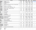
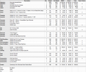
Attached is an excel spreadsheet with the complete Bill-of-Materials (BOM) for this project. It includes price, weight of each item. You can get these parts from numerous places and good deals can be found on ebay if you are patient. For the sake of this effort I have included an amazon price and link for each item to give people an easy reference and source that works most anywhere.

I know we do not like to discuss what our bikes and trikes cost; especially with walkups that are expecting us to say $199.99 but I continue to think the cost numbers are relevant and important for this sort of project for people to understand what they might truly be saving up for. Unlike past years you can now buy a preconfigured V20 for $4500 which is a big time saver and has a really nice set of components. Or you can get the frame kit and build it to your specific goals. The Bill of Materials here will demonstrate that you can build a completely tricked out rig for Under $10k or a very respectable base bike for just over $4k. While $10k might sound like a ton but with Carbon Wonder DF bikes at the top of the spectrum start at $13-15k that's still a very competitive price point. (Referesh point Trek Race Shop Limited, and Specialized S-works).

My personal goal for the project was to reuse high end components and I had from previous bikes (wheels, cranks, power meters) and add in SRAM new E-Tap wireless shifting. After having ridden Shimano's Di2 for a full season; I'm now completely in the electric shifting camp, it's just that much better and lower maintenance. But Di2 wiring is a real pain to execute so when SRAM wireless finally hit the market it was time to give that a try.

The BOM has some basic what-if's that let you move the "x" around to compare different component combination for weight and price. The spreadsheet is not exhaustive by any means but it should provide a starting point that anyone can build on. At the very least it will tell all the items you need to consider so you can figure out what the project will really cost you in the end.

bom1.png bom2.png bom3.png

BOM XLS format https://www.dropbox.com/s/3bvu095il19jyad/vbom.xls?dl=0

BOM XLSX format https://www.dropbox.com/s/73jlrsd9kyhegak/vbom.xlsx?dl=0
 

ratz

Wielder of the Rubber Mallet
The 2016 V20 frame is much the same as the last two iterations.

IMO, the welds are well executive and on par with other high end aluminum frames. and the metal flake paint job is very deep and glossy. Note the frame in these photos are the hand painted limited edition (those were the only frames left in stock when I ordered). Wasn't sure I was going to like those but when they got here I was really impressed with the quality. I was really surprised that the custom paint continued even to the area that will be covered by the seat.

As a nice touch, all the areas that are not suppose to have paint on them, had been covered by stickers that pealed of exposing the bar metal where the bare metal is support to be. The is a nice improvement over my Yellow Vendetta that sometime requires filing and sanding to remove paint from places it wasn't support to be.

The same velcro system is in place to hold the seat pan. Since that's never been a problem on previous versions seems sensible that it remains unchanged on the 2016 version.

DSC05794.jpg DSC05795.jpg DSC05796.jpg DSC05798.jpg DSC05801.jpg
 

ratz

Wielder of the Rubber Mallet
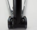
Ok for the final post for today; a quick look at the new chainstay enhancements.

The Geometry of the Stay has remained mostly unchanged, but improved cable routing has been added.

1) There is now a cable stop welded on at the bottom of the front derailleur stem.
2) A cable pulley has been added to the bottom of the stem to reverse the direction of your FD cable.
3) The Stay itself is now slightly wider to better accommodate disc brake hubs and 11 speed drive trains.
4) small recess has been added to the top of the stem to guide the cable back up the boom
5) The derailleur hanger slot has been upgraded to presfit so that the hanger has a better chance to stay put during wheel changes.

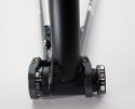
The BB clamps remain unchanged and thus limit the bike to CrankSet with a 24mm spindle. BB30 will not work with these frame nor will and the new internal bearing standards that have been making a comeback.

DSC05819.jpg DSC05818.jpg DSC05816.jpg DSC05821.jpg
 

ratz

Wielder of the Rubber Mallet
Looking at the fork; on the surface it looks mostly unchanged. Since the move away from the Yellow Vendetta, the fork has been widened to accommodate a 132.5mm dropout so that both disc and non disc wheels can be used. The tapper has been increase to allow for 11 speed gearing, and the steam is longer to accommodate larger riders.

The longer stem does mean that shorter riders will need to cut the stem down if they want to see down and over the boom when in a riding position. While that might be a hassle it's perfectly normal in the Diamond Frame world to cut the stem when sizing a bike; it's just too expensive to manufacture and stock a variety of lengths. The bearing set appears unchanged from previous models and the option for disc or rim brakes remains.

Lastly like previous incarnations the fork is by far the heaviest piece of the bike; but since it holds the drive wheel that is mostly expected. Whenever I study these forks I have to stop an marvel at the homebuilders that create them from scrap. The only thing simple about a fork it turn it after it's mounted.

DSC05769.jpg DSC05770.jpg DSC05771.jpg
 

ratz

Wielder of the Rubber Mallet
The boom has gone through several enhancements. There is now very welcomed graduated marking on the boom so that you can remember your configuration and return it should the boom every slip or should you change it to let a pal ride you bike. I for one won't miss the piece of electrical tap I used for that in the past.

The front light mount has has adopted the Silvo mount but has been limited to just one fin, a definite improvement over the Silvio 2.x dual fin.

Down by the bottom bracket a exit hole has been added, another welcome addition that will make it simple to run Di2 wires internally without have to drill hold in the boom.

Lastly as with previous model the BB chases are clean and tidy no need to chase or face the frame before installing the bottom bracket.

DSC05773.jpg DSC05772.jpg DSC05774.jpgDSC05779.jpg
 

ratz

Wielder of the Rubber Mallet
The slider now comes in two varieties. The include straight version and a new optional curved version that can be use to raise or lower the handle position depending on the size of the rider. The slider carries forward the bottle cage braze-ons which is useful; but that also ensures interference from with the boom for short riders. Rider with shorter ex-seams (45inch-ish) will need to cut the boom for it to slide in far enough.

The cutting process is pretty simple with $10 pipe cutter from the hardware store and again probably necessary to allow for large riders without having to stock multiple sets of booms. Took me about 3 minutes to cut off 2 inches from my boom during setup which leaves the frame still able to go larger than my x-seam and just a little shorter than my x-seam. The handle bar clamp remains the same and takes 31.8mm handlebars. But the pivot clamp has been enhanced and now contains the Front Derailleur cable stop and adjuster. A much more sensible place allowing on the fly fine tuning when riding.

Lastly down at the slider clamp there is now a cable guide hole used to send the cable down to the cable top and pivot wheel on the Front derailleur stalk. What is that nice? Well it means if you cable it bypassing the pivot clamp stop you can now change the boom length without having to reset the front derailleur. It does mean will have to handle and manage some excess cable but that subtle improvement should be a boon to those riders that are not their own mechanics or that are in the early boom tuning stages. Still doubtful a LBS would set it up right the first time, but one step at a time. (sorry about the bad curved slider photos I forgot to shoot it so crappy iPhone photos to the rescue).
DSC05776.jpg DSC05775.jpg DSC05777.jpg DSC05778.jpg IMG_5019.jpg IMG_5020.jpg
 
Last edited:

Robert Holler

Administrator
Staff member
Awesome posts. I will add here that when doing a build if you use the cable adjust at the pivot clamp you will effectively make adjusting the boom or slider impossible, as you will have locked the housing onto a part that does not move - like a suspension bridge. On completes, demos, and my personal bike I bypass that and add an inline adjuster closer to the front end.

Robert
 

ratz

Wielder of the Rubber Mallet
As with past incarnations their are numerous included small parts

A) Velcro for attaching the seat pads to the seat pan. Not preinstalled which is nice for those that might be perusing alternative pads like Ventisit seat pads

B) Claps and bolts for attach the top of the seat pan to the headrest poles.

C) Cruzbike wheel skewers, slightly longer than standard.

D) Thinner fork stem spacers (including with the curved sliders)

E) Bolts for attaching the bottom of the seat pan to the frame

F) Extra Pivot Clamp Bolt

G) Pressfit Derailleur hanger and spare.

H) Cable stop and dust covers for "rear" derailleur

J) Bolts and nuts or attaching what bottle holders to the seat pan

K) Cable for those that want to use the legacy front derailleur cable path.

DSC05887.jpg DSC05806.jpg
 

ratz

Wielder of the Rubber Mallet
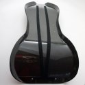
The carbon fiber seat pan is a substantial improvement over the original fiber glass seat. The new one weighs in at a full pound less and is a single piece. Past manufacturing issues have been resolved as the velcro on the bottom of the seat in install in a near perfect position. The seat pan thankfully now comes with pre-drilled holes for the water bottle cages and the top fasteners. These changes where introduce with the Red V20 series.

DSC05765.jpg DSC05763.jpg DSC05766.jpg

The seat cushions are unchanged in shape but the embroidered Cruzbike logo in no longer present. This makes good sense for a several reasons, (1) no one would see the label when he rider is on the bike, (2) the logo has changed (3) the embroidery costs of such a logo add unnecessary cost the bike.

DSC05767.jpg
 

ratz

Wielder of the Rubber Mallet
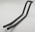
The headrest remains all but completely unchanged since the first hydro formed frames. A single piece of aluminum tubing bent into a surprisingly useful shape. Although some might install padding enhancement, the simple design works well for most riders after they invest the time to get the length set correctly. The one improvement is the rubbers slip covers on the arms. Previous incarnations where cut into 4 different pieces. By changing these to two long pieces installing the head rest into the frame is much easier; and likewise adjustments are also easier. That should mean more people can get the headrest better adjusted for comfort.

DSC05894.jpg DSC05896.jpg
 

ratz

Wielder of the Rubber Mallet
Now with all the frame kit pieces accounted for it's time to assembly the basic frame. First up is install the headrest which start by removing the screws from the scissors clamp. Do not remove the tape from the clamp.

DSC05822.jpg

Not the small notches in the metal pictures. That's the top of the clamp in case you didn't pay attention when you removed the screws. Now fold the clamps in half (well sort in half) as far as you can, narrowing the clamp assembly the long way. Then slide the clamp into the top of the frame.

DSC05823.jpg

You will have to bend it length wise as you ease it in. It will feel like it doesn't want to go in; be patient and gently push until it is in.

DSC05824.jpg

Once it's in the frame gently line up the clamps and insert the bolts. This will be the slowest part of the entire bike assembly. Just go slow and don't strip the screws. For those that haven't built any of the previous versions, it should be noted that this new setup is 1000% easier and better than the old versions for frame that have the metal plate on the back (aka the hyrdo-formed frame). This works and is reliable, the old style just induced swearing. It's a subtle evolutionary improvement that likely didn't increase the production costs.

DSC05825.jpg

With the screws in place as pictured. Put your fingers in the frame and hold the outside edges of the clamps. Then push the screws into the frame so that the clamps pivot open. Then slide the headrest into the frame; wiggle it left and right and it will slowly slide in. Be careful to not tear or fold the rubber selves on the pipes. Leave about 1 in of the rubber out of the frame for the time being. Then tighten down the bolts to anchor the headrest

DSC05828.jpg

Once the bike is completely assembled the head rest can be adjust by loosening the screw just a bit and then wiggling the headset to slide it out. After you have a couple hundred miles on the bike and the headrest dialed in; I would suggest sealing the area around the headrest pipe where they enter the frame with some clear bathroom caulk or similar. If you don't do that wet road dirt will accumulate on the headrest and then percolate into the frame and you wind up with a pile of sand in the bottom of the frame by the end of the season.
 

ratz

Wielder of the Rubber Mallet
Installing the fork is next up. First make note of the order of the bearing stack on the fork.

DSC05771.jpg

Remove the end cap with an allen wrench, then remove all pieces except for the silver split ring.

DSC05829.jpg

To prep the frame to accept the fork; you need to apply liberal grease to the frame bearing cups top and bottom. This grease is not applied so that the fork can turn; rather this is the grease that allows you two tighten the fork assembly with a light torque to remove all vertical play. Without the grease you will not get a snug fit and the fork move around in the frame causing all sorts of future problems.

DSC05830.jpg

Returning to the fork. Press the silver split ring onto the crown nice and tight. Then apply grease to the top edge of the ring. Again this is fitting grease not turing grease.

DSC05831.jpg

With that prep work done; slide the bottom bearing in place as pictured.

DSC05833.jpg
 

ratz

Wielder of the Rubber Mallet
Before installing the fork into the frame. Locate the boom and remove the pivot clamp. Once that is removed find the two fork spacers. You will need both parts to complete the installation of the fork and you don't want to be looking for them halfway through the process.

DSC05838.jpg
DSC05840.jpg

Now study your fork and determine the front and back. The cable stops are on the back side if you are unsure. With all of that prepared insert the fork into the from from the bottom.

DSC05834.jpg

After the fork is in the frame; install the rest of the bearing stack. First the upper bearing, then the gold split ring (grease the curved side) and then the dust cover.

DSC05835.jpg

Gently press everything together and snug it up with your hands.

DSC05836.jpg

Rotate the fork so that it is correctly align front and back. In that orientation install the two spacers and then the pivot clamp on the top of the stem.

Install the top cap into the fork star nut. Gently tighten it to align and seat all the bearings. Tighten is until it is snug enough to pull everything together but not so tight that it impedes the free turning of the fork. Check the fork to make sure it doesn't bind or rock in the frame.

Once you are sure it's secured correctly. Align the fork facing forward, and the pivot clamp with the two bolts facing backward; and then tight the two bolts down to lock the pivot clamp in alignment with the fork. You may need to adjust this some when the boom installed.

DSC05844.jpg
DSC05850.jpg
 
Last edited:

ratz

Wielder of the Rubber Mallet
One of the boom enhancements introduced back when the Silvio 2.1 was release; was water bottle brace-ons on the slider near the handlebars. The Vendetta V20's inherent this style of boom, albeit of larger diameter and greater stiffness. While these braze-ons are very useful; they do prevent the slider from being able to take up the full length of the boom. Because of this shorter riders will need to cut the boom to allow it to be inserted far enough for their X-seam.

If you know you need to cut your boom now is the time to do it. If you are unsure how much, you should wait until the bike is assembled with pedals and test it before you do any cutting. Experienced owners with other bikes can use the the following calculations adapted from the Silvio 2.1 manual. Sitting on a chair, measure from the floor to the top of your knee example: 58 cm. Add your crank length, example 17cm for 170mm cranks for a total of 75cm. Then add the desired knee clearance at the handlebars say 5cm for a total of 80cm. If those are your calculations then you need to be able to shorten the boom-slider assembly to be 80cm from handle bar bracket to the center of the Bottom Bracket.

Here is an example of measuring that distance on a fully assembled Silvio.

Cut Boom - 6 of 7.jpg Cut Boom - 7 of 7.jpg


Separate the slider and the boom, by loosening the slider clamp, and install the Slider into the frame. Cut Boom - 1 of 7.jpg

Cut Boom - 2 of 7.jpg
Cut Boom - 3 of 7.jpg


Take the boom and mount into a proper vice and use a two inch pipe cutter to remove the appropriate amount of length from the end of the boom. Be sure to cut the Boom and not the slider.

Cut Boom - 4 of 7.jpg

Cut Boom - 5 of 7.jpg

Be sure to de-bur the end of you cut with a tool or sand paper.
 

ratz

Wielder of the Rubber Mallet
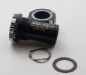
Before you can install the boom and the chainstay to the frame you need to install the boom bracket which will join the boom and the chainstay together. For this build we are using an Enduro XD-15 BB from realworld cycling. Notice the wave washer we'll discuss that when the cranks are installed.

Install Bottom Bracket - 1 of 7.jpg

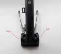
Be sure to consider which is the right side and the left side of your bottom bracket and the corresponding sides of the boom. Align the chain stay and the boom together.

Install Bottom Bracket - 2 of 7.jpg
Install Bottom Bracket - 3 of 7.jpg
Apply liberal grease on the threads inside the bottom bracket shell in the boom. Then install the drive side of the bottom bracket and carefully thread the bearing cup into the shell being sure not to cross thread. Then slide the assembly to the side and install the dust sleeve and the left side cup.

Install Bottom Bracket - 4 of 7.jpg

using a proper torque wrench correctly torque the cups into the shell. Be sure to not the arrow on the cups that indicate which way to tighten them. Which in both cases is top towards the seat area.

Install Bottom Bracket - 5 of 7.jpg

Verify the fit; but do not tighten the cup clamps bolts at this point,

Install Bottom Bracket - 6 of 7.jpg
Install Bottom Bracket - 7 of 7.jpg
 

ratz

Wielder of the Rubber Mallet
Now that the boom and chainstay are attached via the bottom bracket; it is time to assemble the front triangle. Install the boom into the the slider and tighten the clamp so that it pinches the compression notch. Snug is good enough for now and don't worry about the total length.
Assemble front triangle - 1 of 8.jpg
Assemble front triangle - 2 of 8.jpg

The chain stay should now hangs freely from the bottom bracket.

Assemble front triangle - 3 of 8.jpg

Rotate the chain stay and connect it toe the fork hoods.

Assemble front triangle - 4 of 8.jpg
Assemble front triangle - 5 of 8.jpg

You will need to spread the chain-stay ever so slightly to get it around the forks. At this point the triangle will stay together by itself. If you need to besure of that you and install the front skewer to hold it all together.

Assemble front triangle - 6 of 8.jpg
Assemble front triangle - 7 of 8.jpg
Assemble front triangle - 8 of 8.jpg
 

ratz

Wielder of the Rubber Mallet
If you haven't decided on Rims yet and you don't have your eye on very high-end rims and hubs; then you really should get the A67 Rims from Cruzbike. They are machine made 24/28 spoke Rims with bladed spokes and decent hubs. At $375 it's rather impossible to find a set of wheels cheaper unless you go with no-name clones from some of the east-asian markets. While good wheels can be had that way it does require more diligent research and higher risk. For comparison a pair of flow 30's will run your $448 if you can get them and it's arguably a very similar wheel.

Prep Rims - 1 of 5.jpg

When you get A67's from Cruzbike they include Orgin8 rim tape/straps.

Prep Rims - 2 of 5.jpg

To install the the rim straps, find the rim stem hole, and slide a tube valve through the hole in the strap and the rim.

Prep Rims - 3 of 5.jpg

Use a stem nut to hold the valve in the rim. Work the strap around the rim,

Prep Rims - 4 of 5.jpg

As you get to the far side, the strap will get tight and you'll need to snap it into place; being careful not to twist it as it snaps into place.

Prep Rims - 5 of 5.jpg
 

ratz

Wielder of the Rubber Mallet
Grab your favorite tire; in this case it's Conti GrandPrix 4000s II. This is a directional tire and need to be install the correct way. If you have a directional tire, make sure you know which way is forward on the wheel. Astute readers will notice that the following wheel is mounted backwards which let to some 3 and 4 letter phrases in the shop.

Install one side of the wheel on to the rim.

Mount Tires - 1 of 4.jpg

Lightly inflate the tube.

Mount Tires - 2 of 4.jpg

Install the tube and valve into the rim, and fasten it with the nut. Then gently work the tube into the tire body and over the rim.

Mount Tires - 3 of 4.jpg

Starting with at the stem work the second side of the tire on to the rim. When you get to the far side it will bind and you will have to twist the final part over the rim for a good seating.

Mount Tires - 4 of 4.jpg

At that point slowing inflate the tire checking where the rim and tire meet to make sure the tube isn't pinched.

Mount Tires - 1 of 1.jpg
 
Top